Type Name: urc
The urc model is derived from a model proposed by L. Gertzberrg in 1974. The model is generated by a subcircuit type expansion of the urc line into a network of lumped RC segments with internally generated nodes. The RC segments are in a geometric progression, increasing toward the middle of the urc line, with k as a proportionality constant. The number of lumped segments used, if not specified on the urc line, is determined by the following formula:
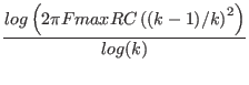
where Fmax is the maximum frequency, and R and C are the total values for the given length.
The urc will be made up strictly of resistor and capacitor segments unless the isperl parameter is given a non-zero value, in which case the capacitors are replaced with reverse biased diodes with a zero-bias junction capacitance equivalent to the capacitance replaced, and with a saturation current taking the value given isperl in amps per meter of transmission line, and with an optional series resistance specified by rsperl in ohms per meter.
URC Model Parameters name parameter units default example k propagation Constant - 1.5 1.2 fmax maximum frequency of interest Hz 1.0G 6.5meg rperl resistance per unit length /M
1000 10 cperl capacitance per unit length F/M 1.0e-12 2pf isperl saturation current per unit length A/M 0 - rsperl diode resistance per unit length 0 -