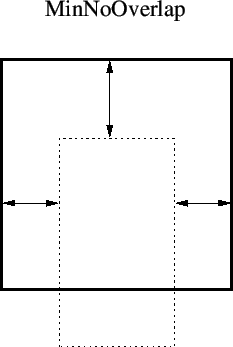
next up previous contents index
Next: Assigning Design Rules Up: The DRC Menu: Design Previous: Spacing Table Evaluation   Contents   Index


User-Defined Design Rules

This section describes the facility for defining and referencing user-specified design rules. These allow complex tests to be implemented. User-defined rules are defined in separate blocks ahead of the physical layer specification blocks in the technology file. The rules are referenced from the layer blocks. A user defined rule definition has the following general form:

DrcTest testname arg1 arg2 ...
Edge Outside|Inside expression
MinEdge dimension
MaxEdge dimension
Test Outside|Inside dimension expression
TestCornerOverlap dimension
Evaluate logical_expression
[ script lines ]
End

The first line of the block starts with the keyword DrcTest. This is followed by a name for the test, which must be unique among the keywords recognized in the technology file. This is the name by which the test will be referenced. Following the name are zero or more argument tokens. These can be any alphanumeric text strings, which represent parameter names. These are the formal arguments to the rule, and appear in the lines that follow in the form ``%token%'', which will be replaced by the actual arguments given in the references to the rule.

The rule is evaluated at each edge of the source. Each edge is divided into segments, depending on specifications. For each segment, a rectangle is constructed, extending either into or out of the source figure. Tests are applied to these regions,

The Edge keyword indicates an edge specification. There can be zero or more edge specifications. Following the Edge keyword is one of the keywords Outside or Inside followed by a layer expression. When the edge is evaluated the regions of the edge where the expression is true are found, either just inside or just outside of the figure. The default edge is the set of regions where there is no source figure just outside the edge, which means that there is no source-compatible adjacent figure. The results from each Edge specification are anded together with the default edge to determine the segments where tests are performed. The expression part of the Edge specification can contain argument substitutions.

For example:

Edge Inside M2
This will include the parts of the figure boundary that 1) do not touch or overlap another figure of the same source (the default edge), and 2) have layer M2 present on the inside side of the boundary. The default edge is always implicitly included in the conjunction.

The MinEdge and MaxEdge lines, which are optional, allow setting limits on the segments used for testing. If given, an edge segment used for testing would have length greater or equal to the MinEdge dimension, and less than or equal to the MaxEdge dimension. The dimensions appearing after the keywords can contain argument substitutions.

There must be one of more lines given which start with the keyword Test. These specify the tests which are applied to regions constructed from the edge segments. Following Test is one of the keywords Outside or Inside, which determines whether the test area extends outside or inside the source figure. The following token, which can contain an argument substitution, sets the length by which the test area extends out of or into the source figure. The rest of the line contains a layer expression, which can contain argument substitutions, which is evaluated in the test area.

The expression will be evaluated within the test area by one of the evaluation functions described below. If using the most common DRCuserTest evaluation function, The test is true if the expression is true somewhere in the test area, meaning that there is a non-zero area where the logical expression would be ``dark''.

For example:

Test Outside 0.5 !M2
This test will be ``true'' if within the rectangle extending out of the figure from the edge by 0.5 microns, there is some point where layer M2 is not present, if using DRCuserTest.

The optional TestCornerOverlap is a special supplemental test when evaluating ``MinWidth''. This measures the mutual edge or overlap of adjacent compatible figures. The width of the mutual edge must be greater than the dimension (which can contain argument substitutions).

The final line, which begins with the keyword Evaluate, specifies a logical expression or script. There are two forms for the Evaluate construct. In the first form, the expression must be cast as an assignment to a variable named ``fail'', and if set true the entire rule fails. Argument substitutions are allowed in the expression. The assignment must appear on the same line following Evaluate.

In the second form, there can be no additional text on the line following Evaluate. The following lines contain a script, in the format understood by the script parser. This is terminated with the keyword EndScript. Argument substitutions are allowed in these lines. The script can contain any of the constructs described in the manual section on the script parser, with the exception of the ``preprocessing'' directives; any line with a leading `#' is ignored. The script should set a variable named ``fail'' to signal a DRC violation.

There are several functions which can appear in the Evaluate lines. Each of these functions takes a single integer argument. This is a zero-based integer index corresponding to the Test lines, in order of their appearance. Each function returns a value obtained from the corresponding test.

The functions currently available are the following:

(int) DRCuserTest(index)
The return value is 1 if the test region is not empty, 0 otherwise.

(int) DRCuserEmpty(index)
The return value is 1 if the test region is empty, 0 otherwise.

(int) DRCuserFull(index)
The return value is 1 if the test region is completely covered, 0 otherwise.

(zoidlist) DRCuserZlist(index)
The return value is a list of trapezoids clipped from the test region. The list can be used with script functions that operate with this data type.

(int) DRCuserEdgeLength(index)
The return value is the length along the edge of the test region. This is the value that is filtered by MinEdge and MaxEdge. Filtered edges will not be seen by this function.

The functions specified are called for each test region for each edge and corner. The return value can be used to set the fail variable. Once the fail variable has been set nonzero, testing of the object terminates for the present rule.

For example:

Test Outside 0.5 !M2
Test Inside 0.5 !M2
Evaluate fail = DRCuserTest(0) | DRCuserTest(1)
Here, the test fails if M2 does not completely cover the area 0.5 microns on either side of the edge. The arguments to the DRCuserTest function refer to the Test lines: 0 is the first Test line in the rule, 1 the second, and so on.

The multi-line variation of the Evaluate clause has the form

Evaluate
script line
...
EndScript

Within the script, there are a number of predefined variables available. With the exception of fail, these all start with an underscore.

_ObjType
The type of object which is undergoing DRC. Values are 'p', 'w', or 'b', for polygons, wires, and boxes.

_ObjNumEdges
This is the number of vertices in the figure being tested. Boxes and wires are converted to polygons for testing, so this makes sense for all objects. The first and last vertices are the same, and all are counted, so that the number of vertices in a box is five.

_CurEdge
This is the zero-based index of the edge or vertex currently being tested. If the original object is a box, the zeroth vertex is the lower-left corner, and the zeroth edge is the left edge. For polygons, the zeroth vertex is the first vertex in the polygon's coordinate list, and the zeroth edge extends from this vertex to the next. This index will cycle through the values from 0 to _ObjNumEdges-1. Values may be skipped of there is no testable area at the edge or corner.

If a test is identified as a ``MinWidth'' type, i.e., an inside test with the target the same as the source, at most two edges are tested if the figure is a box.

_CurTest
This gives the following values: 0 if the test is a standard edge test, 1 if the test if a corner test, and 2 if the test is the CornerOverlap test.

_CurX1, _CurY1, _CurX2, _CurY2
These four variables provide the starting and ending coordinates of the edge segment being tested, in microns.

Variables defined within the script remain in scope forever, they do not change between calls.

When an object is DRC tested, the Overlap tests, if any, are first applied to the source region. This is followed by the Area tests, then the edge tests, which include any user-defined tests. During the edge tests, each edge is evaluated in sequence. The test may be applied several times for different regions along the edge or not at all, depending on the geometry and the Edge specification.

Edge segments are evaluated in the order crossed by a point following the boundary starting at the first vertex (lower left corner for boxes). Boxes and wires always have clockwise winding, though polygons can have either clockwise or counterclockwise winding.

Associated with the edge test are the corner tests. For a box, the order of tests is given below. The corner test is applied at each vertex (if indicated by the angle) after the previous adjacent side has been tested. The test area is a polygonal shape designed to ``fill in'' gaps between the rectangular areas associated with the sides.

_CurEdge _CurTest which
0 0 left edge
1 1 upper left corner
1 0 top edge
2 1 upper right corner
2 0 right edge
3 1 lower right corner
3 0 bottom edge
0 1 lower left corner

A rule is implemented by adding a reference to the rule in the layer block of a physical layer. The format is

testname [Region region_expr] [arg1 arg2 ...] [string]

The testname is the keyword defined in one of the rule definitions, as described above. This is followed by an optional source specification, and the actual arguments, which must correspond in number to the rule arguments. These are followed by an optional string, which is arbitrary explanatory text.

As initial examples, below are implementations of the built-in rules which involve edge evaluation.

These are the rule definitions, and by convention they appear in the technology file after the electrical layer definitions and ahead of the physical layer definitions.

# In the first two rules, lyr is the same as the source
#
DrcTest myMinWidth dim lyr
Test Inside %dim% !%lyr%
TestCornerOverlap %dim%
Evaluate fail = DRCuserTest(0)
End

DrcTest myMinSpace dim lyr
Test Outside %dim% %lyr%
Evaluate fail = DRCuserTest(0)
End

# In the remaining rules, lyr is different from the source
#
DrcTest myMinSpaceTo dim lyr
Edge Inside !%lyr%
Test Outside %dim% %lyr%
Evaluate fail = DRCuserTest(0)
End

DrcTest myMinSpaceFrom dim lyr
Edge Inside %lyr%
Test Outside %dim% !%lyr%
Evaluate fail = DRCuserTest(0)
End

DrcTest myMinOverlap dim lyr
Edge Inside %lyr%
Test Inside %dim% !%lyr%
Evaluate fail = DRCuserTest(0)
End

DrcTest myMinNoOverlap dim lyr
Edge Inside !%lyr%
Test Inside %dim% %lyr%
Evaluate fail = DRCuserTest(0)
End

To implement the rules, references are added to the layer definitions:

Layer M1
...
myMinWidth 3.0 M1
myMinSpace 2.0 M1
myMinSpaceTo 1.0 M2
...

Here are some examples of more complicated rules:

Rule: Objects on M3 smaller that 10 microns must be separated by .5 microns or more, Objects larger than 10 microns must be separated by .75 microns or more.

DrcTest myMinSp1 lyr
# Fail if spacing < 0.5
Test Outside .5 %lyr%
Evaluate fail = DRCuserTest(0)
End

DrcTest myMinSp2 lyr
# Fail if spacing < 0.75 and width > = 10
MinEdge 10
Test Outside .75 %lyr%
Test Inside 10 !%lyr%
Evaluate fail = DRCuserTest(0) & !DRCuserTest(1)
End

Layer M3
...
myMinSp1 M3
myMinSp2 M3
...

Note that we did not need to use substitution here, as the rule only applies to M3.

Rule: Objects on M3 must be larger than 1 micron, unless over I1 in which case the width must be 1.25 microns.

DrcTest myMinW1 lyr
# Fail if width < 1.0
Test Inside 1 !%lyr%
TestCornerOverlap 1
Evaluate fail = DRCuserTest(0)
End

DrcTest myMinW2 lyr
# Fail if width < 1.25 and I1 present
Test Inside 1.25 !%lyr%
Test Inside 1.25 I1
TestCornerOverlap 1.25
Evaluate fail = DRCuserTest(0) & DRCuserTest(1)
End

Layer M3
...
myMinW1 M3
myMinW2 M3
...

Rule: The overlap of M1 surrounding Via must be .5 microns or greater. Only two sides maximum can have an overlap of less than 1 micron, the other sides must have 1 micron of overlap or more.

In the script below, two arrays are defined, to hold the test results. We assume that only boxes are used for vias, and ignore the corner tests. When the final edge (_CurEdge = 3) is reached, the results saved in the arrays are evaluated, and the fail flag is set if an error is indicated.

DrcTest vtest
Test Outside 1 !M1
Test Outside .5 !M1
Evaluate
tl[4]
ts[4]
if (_ObjType == 'b' & _CurTest == 0)
    tl[_CurEdge] = DRCuserTest(0)
    ts[_CurEdge] = DRCuserTest(1)
    if (_CurEdge == 3)
        if (tl[0] + tl[1] + tl[2] + tl[3] > 2)
            fail = 1
        end
        if (ts[0] + ts[1] + ts[2] + ts[3] > 0)
            fail = 1
        end
    end
end
EndScript
End

The test is implemented in the Via layer block. Just the keyword is needed, since no arguments are passed.

Layer Via
...
vtest


next up previous contents index
Next: Assigning Design Rules Up: The DRC Menu: Design Previous: Spacing Table Evaluation   Contents   Index
Stephen R. Whiteley 2022-05-28